TV Inspection Fields
The following fields appear on the General
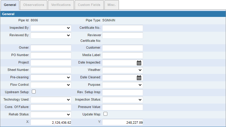
- Pipe Id: This field automatically populates with the ID associated to the selected asset.
- Pipe Type: This field automatically populates with the attribute of the selected pipe ID.
- Inspected By: Select the employee who performed the inspection.
- Certificate No: Enter the PACP certification number for the contractor performing the inspection.
- Reviewed By: Enter the name or initials of the PACP® certified user responsible for reviewing or post-processing the survey and a standard abbreviation of the company name.*
- Reviewer Certificate No: Enter the PACP® user certification number of the individual named in the Reviewed By field. The purpose of this field is to uniquely identify the individual responsible for reviewing the survey.*
- Owner: Enter the owner of the system.
- Customer: Enter the customer name.
- PO Number: Enter the PO number.
- Media Label: The media number should be entered at the start of the survey. The entity performing the inspection issues the media labeling, unless otherwise instructed by the Customer. All surveys should be recorded to allow for review and quality control of the coding. Also, the video should be available for review to make rehabilitation decisions.*
- Project: Enter the name of the project in which the inspection belongs.*
- Date Inspected: Enter the date of the inspection or select it using the calendar.
- Sheet Number: Hand-written surveys may continue onto more than one sheet of paper forms. Where this is the case, the sheet number must be entered. Sheets are numbered consecutively.*
- Weather: Select the weather during the time of the inspection.
- Pre-cleaning: Select from the Pre-cleaning drop-down list whether or not cleaning was completed before the inspection.
- Date Cleaned: Enter the date cleaned or select it using the calendar.
- Flow Control: Enter the means used to block the flow during inspection if something was used.
- Purpose: Select the purpose of the inspection.
- Upstream Setup: Select the check box if the inspection was done in the upstream direction.
- Rev. Setup Insp: If the television inspection of an entire section (manhole to manhole) cannot be successfully performed from one manhole, a reverse setup shall be performed per PACP requirement as a second survey. Both of these inspections shall be displayed as a single report in Pipe Graphic and Tabular Reports.
- Technology Used: Select the technology used to inspect the pipe segment.*
- Inspection Status: Select the status of the inspection.
- Cons. Of Failure: The consequence of failure rating of the particular pipe are provided by the Customer and may not be known by the Operator at the time of the survey. The consequence of failure is an asset management term and is determined by considering the financial, social, and environmental impacts of failure of the section of pipe being surveyed.*
- Pressure Value: If joint or lateral testing is conducted, enter the specified minimum testing pressure with accuracy up to three decimal places. The unit of measurement shall be pounds per square inch (psi in imperial units) or kilo (kPa in metric), matching the pressure used for the Grout Test and Seal group of codes.*
- Rehab Status: Select the rehab status. The content of this list is populated by the administrator in Designer under Preferences > Custom Codes > SRSTAT.
- Update Map: This field can be used as a flag for whatever purpose your organization wishes. For example, it could be used for instances when the map or GIS need to be updated. The administrator can search for inspections that have this field selected. The name of the field can be changed by editing the corresponding XML file.
- X/Y: The
The following fields appear in the Location

- Drainage Area: Enter the Common name given to the drainage area or sewer basin provided by the Customer.
- Street: Enter the street number or name of the starting access point. If the street name is not known, enter the place name and a general description of the location. The purpose of this field is to allow the proximity of the access point to be found using a database of known street addresses, similar to the approach used by GPS devices.*
- City: Enter the name of the city or town where the pipe is located. This may be different from the Owner's name, if the utility operates across governmental boundaries.
- Location Code: Select the location, or ground cover, above the pipe being inspection.*
- Location Details: Enter further details on the location, for example, back yard under a deck. Use permanent landmarks and buildings for reference instructions to help locate structures in the future.*
The following fields appear in the Pipe
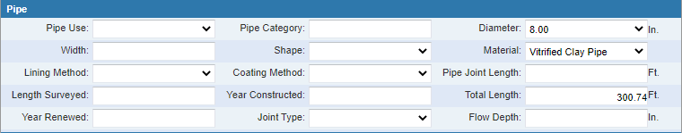
- Pipe Use: Select the use of the pipe, usually either sewer or storm.
- Pipe Category: Enter the category.
- Diameter: This dimension is the estimated pipe height (diameter) at the manhole wall, estimated to the nearest whole inch or millimeter or to the level of accuracy dictated by the survey Customer. The content of this list is populated by the administrator in Designer under Preferences > Custom Codes > SDIAM.*
- Width: Enter the maximum pipe width (if not circular). This dimension is the approximate pipe width at the manhole wall, estimated to the nearest whole inch or millimeter or to the level of accuracy dictated by the survey Customer.*
- Shape: Select a description of the pipe.*
- Material: This field is used to record the predominate pipe material used during original construction of the segment, not necessary the pipe material where the inspection starts. The content of this list is populated by the administrator in Designer under Preferences > Custom Codes > SPIPEMT.*
- Lining Method: Select the lining system for rehabilitated pipes. The content of this list is populated by the administrator in Designer under Preferences > Custom Codes > SLMETHOD.*
- Coating Method: This field is used to described pipes where a protective coating system has been applied, commonly by the manufacturer of the pipe material. A coating system can therefore be defined as any material that is applied to the original pipe before installation. These coatings can be polymer-based, cement, coal tar, or other.*
- Pipe Joint Length: Enter the length between joints of an average pipe, i.e. each individual pipe section. Do not base this length on partial pipe sections, which are often adjacent to a manhole.*
- Length Surveyed: Enter the distance actually surveyed. If the survey is abandoned, enter the actual length surveyed, i.e. the distance displayed on the counter.*
- Year Constructed: Enter the actual year the pipe was constructed, if known.*
- Total Length: This distance from the wall of the starting access point to the wall of the finishing access point.*
- Year Renewed: Enter the actual year the pipe was rehabilitated/relined, if known.*
- Joint Type: Select the type of joint. The content of this list is populated by the administrator in Designer under Preferences > Custom Codes > SJOINT.
- Flow Depth: Enter the flow depth, in feet.
The following fields appear in the Measurements section:
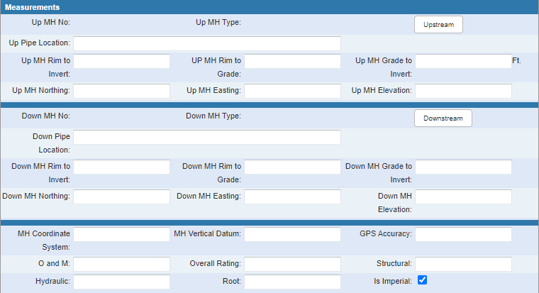
- Up MH No: Enter the reference number for the access point as given in an established local access point referencing system.*
- Up MH Type: This field automatically populates with the feature type of the upstream ID.
- Up Pipe Location: Enter the location of the upstream feature. This field automatically populates with the upstream ID.
- Up MH Rim to Invert: Enter the distance between the rim level of the manhole (or access point) and the invert level of the pipe being surveyed. This must be physically measured by the technician on site being surveyed.*
- Up MH Rim to Grade: Enter the depth between the rim of the manhole and the grade (ground) level.*
- Up MG Grade to Invert: Enter the distance between the grade (ground) level and the pipe invert level. This field must be calculated by subtracting Up MH Rim to Grade from Up MH Rim to Invert.*
- Up MH Northing: Enter the latitude at the center point of the upstream manhole (or access point). If a value is entered in this field, Up MH Easting and MH Coordinate System must also be entered.*
- Up MH Easting: Enter the longitude at the center point of the starting access point. If a value is entered, Up MH Northing and MH Coordinate System are also required.*
- Up MH Elevation: Enter the elevation at the center point of the cover of the starting access point.*
- Down MH No: Enter the reference number for the manhole (or access point) as given in an established local access point referencing system.*
- Down MH Type: This field automatically populates with the feature type of the downstream ID.
- Down Pipe Location: Enter the location of the downstream feature. This field may automatically populate with the downstream ID.
- Down MH Rim to Invert: Enter the distance between the rim level of the downstream manhole (or access point) and the invert level of the pipe being surveyed.*
- Down MH Rim to Grade: Enter the distance between the rim of the downstream manhole (or access point) and the grade level. *
- Down MH Grade to Invert: Enter the distance between the grade (ground) level at the downstream manhole (or access point) and the invert of the pipe being surveyed.*
- Down MH Northing: Enter the latitude at the center point of the downstream manhole (or access point). If a value is entered in this field, Down MH Easting and MH Coordinate System must also be entered.*
- Down MH Easting: Enter the longitude at the center point of the downstream access point. If a value is entered, Down MH Northing and MH Coordinate System are also required.*
- Down MH Elevation: Enter the elevation at the center point of the cover of the downstream access point.*
- MH Coordinate System: Enter the geographic reference system used for the GPS X and Y coordinates. If a value is entered, Northing and Easting are also required.*
- MH Vertical Datum: Enter a specific geodetic system for the GPS vertical. If a value is entered here, the elevation in either the Up MH Elevation or Down MH Elevation field is required.*
- GPS Accuracy: Describe the degree of accuracy obtained from coordinates.*
- O and M (Operations and Maintenance): Only applies to TV inspections that are based on the PACP codes used when the Use CCTV Codes preference is active, in which case Hydraulic and Root do not apply.
- Overall Rating: The total condition rating which takes into account the Structural, Hydraulic, and Root ratings for standard inspections, or the Structural and O an M ratings for CCTV codes.
- Structural: Enter the rating for the structural integrity of the system.
- Hydraulic: Enter the rating to indicate the amount of inflow and infiltration (I/I) or unwanted flow into the system.
- Root: Distresses caused by roots are used to calculate this field.
- Is Imperial: Select Is Imperial if all measurements are in calculated using the Imperial system.
The Comments
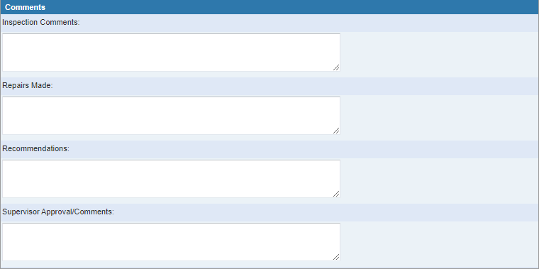
- Inspection Comments: Enter any additional information about the inspection.
- Repairs Made: Enter any details about repairs that were made.
- Recommendations: Enter any recommendations about further work that is needed.
- Supervisor Approval/Comments: Enter comments from the supervisor's review.
The Observations store the pipe defects and other properties captured from the CCTV video. Most defects are the result of one of these three causes: structural, roots, or I/I (inflow and infiltration). Setting this value determines which of the three correlated condition values are updated. If using the PACP grading system, the choices are structural for changes (such as roots, cracks, or collapses) or O&M (Operations & Maintenance) for internal blockages. The Cause options are based on whether the domain administrator has selected the Use CCTV Codes check box in Designer under Preferences > Inspection.
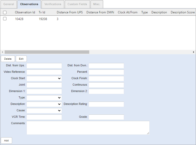
- Dist. from Ups.: Enter the distance of the defect from the node if the camera is traveling upstream.
- Dist. from Dwn.: Enter the distance of the defect from the node if the camera is traveling downstream.
 NOTE: Enter either an upstream or downstream measurement for each observation. There may be both upstream and downstream measurements for a pipe if there is an obstruction that stops the camera and the inspection is continued from the other direction.
- Video Reference: Enter what the counter says in the video to link the defect to the right spot in the video.
- Percent: Enter the percentage of the pipe that is affected by the defect.
- Clock Start: Select the clock position where the defect begins. Values in the Clock Start drop-down list are defined in Designer under Preferences > Custom Codes > STVOBPOS.
- Clock Finish: Enter the clock position where the defect ends.
- Joint: Enter Yes or No to indicate if the defect is near the joint.
- Continuous: Enter how far the defect continues.
- Dimension 1: Enter the dimensions, length and width, of the defect.
- Dimension 2: Enter the dimensions of the connecting pipes or the dimensions of the intrusion of the connecting pipe.
- Type: Select the type of defect.
- Description
- Cause: Select the cause.
NOTE: PACP users have the choice between STRUCTURAL and O&M (Operations & Maintenance). For non-PACP users, the hard-wired options are STRUCTURAL, I/I (Inflow/Infiltration), and ROOT.
- VCR Time: Enter the time marker within the video that the observation can be seen.
- Grade: Enter the numerical representation of the slope or gradient of the pipe.
- Comments: Enter any comments about the defect.
A dye or smoke test is frequently used to identify a problem and a TV crew is sent out to verify the results. The Verifications tab stores a link to the related dye or smoke test performed on the same pipe along with a flag identifying the confirmation of the defect. A few details from the dye or smoke test also appear on the tab, along with the ID so the user can review the test results if desired.
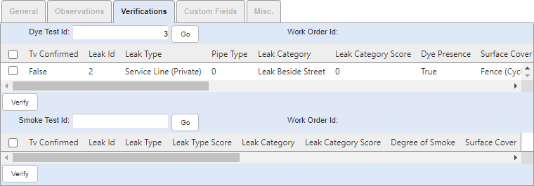
- Dye Test Id: Enter the ID associated with the dye test inspection.
- Go: Click to add the ID.
- Verify: Click to verify the dye test.
- Smoke Test Id: Enter the ID associated with the smoke test inspection.
- Go: Click to add the ID.
- Verify: Click to verify the smoke test.
The Misc. tab contains information about the video tape and taping conditions. Different types of videos can be attached to a TV inspection.
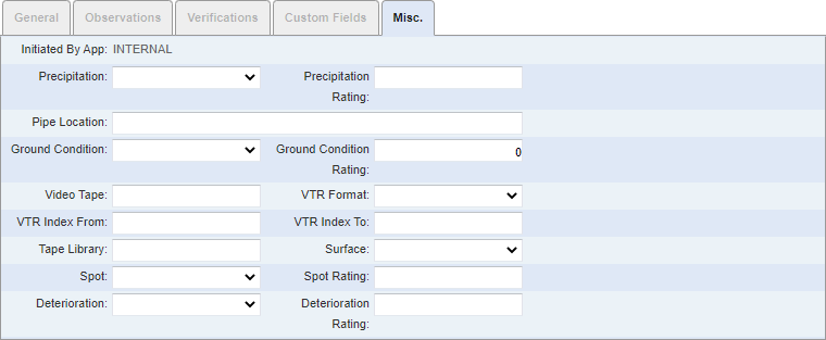
- Initiated By App: This field is uneditable and displays whether the inspection was created manually within Cityworks, or by an import of information from the CCTV Interface.
- Precipitation and rating: Select the precipitation type. A score is assigned when the precipitation type is selected. The contents of this list and scores are populated by the administrator in Designer under Preferences > Description Scores > SPRECIP.
- Pipe Location: Enter the location. This field may automatically populate with the pipe ID.
- Ground Condition and rating: Select the ground condition. A score is assigned when the ground condition is selected. The contents of this list and scores are populated by the administrator in Designer under Preferences > Description Scores > SGRNDCND.
- Video Tape: Enter the name of the tape.
- VTR Format: Select the Video Tape Recorder (VTR) format. The content of this list is populated by the administrator in Designer under Preferences > Custom Codes > SVTRFMAT.
- VTR Index From: Enter the numeric value of the index from.
- VTR Index To: Enter the numeric value of the index to.
- Tape Library: Enter the location of the library where the video is stored.
- Surface: Select the type of surface. The content of this list is populated by the administrator in Designer under Preferences > Custom Codes > SSURFC.
- Spot and rating: Select the spot. A score is assigned when the spot is selected. The contents of this list and scores are populated by the administrator in Designer under Preferences > Description Scores > SSPOT.
- Deterioration and rating: Select the level of deterioration. A score is assigned when the deterioration is selected. The contents of this list and scores are populated by the administrator in Designer under Preferences > Description Scores > SDETERIO.
*These field descriptions were either directly copied or paraphrased from the NASSCO "Pipeline Assessment Certification Program," Version 7.0.3 (January 2018): Sections 1 and 2.